




Total129related FAQs
Phone
Online


Send email


Total129related FAQs
What service models does the company offer for different types of clients (such as brand owners, agents, and end users)?
* Brand Owners: We provide OEM/ODM custom development, branded production, quality management, and product upgrade support. * Distributors: We offer support for market development and product selection, sales guidance, technical training, and reliable supply of products and spare parts. * End Users: Focusing on specific operational conditions, we deliver comprehensive solutions that encompass "operational analysis and customized planning + supply of complete equipment and project implementation + full-lifecycle technical services."
What support and guarantees does the company provide for overseas and international clients?
Leveraging a professional international trade team and a robust supply chain, our products are exported extensively to numerous countries and regions across Asia, the Middle East, Africa, Europe, and South America. We provide international clients with comprehensive support—including multilingual communication, technical documentation, customized design, international logistics, installation guidance, and remote after-sales service—to ensure the efficient execution of their projects.
What equipment is included in the company’s core product and system solution portfolio?
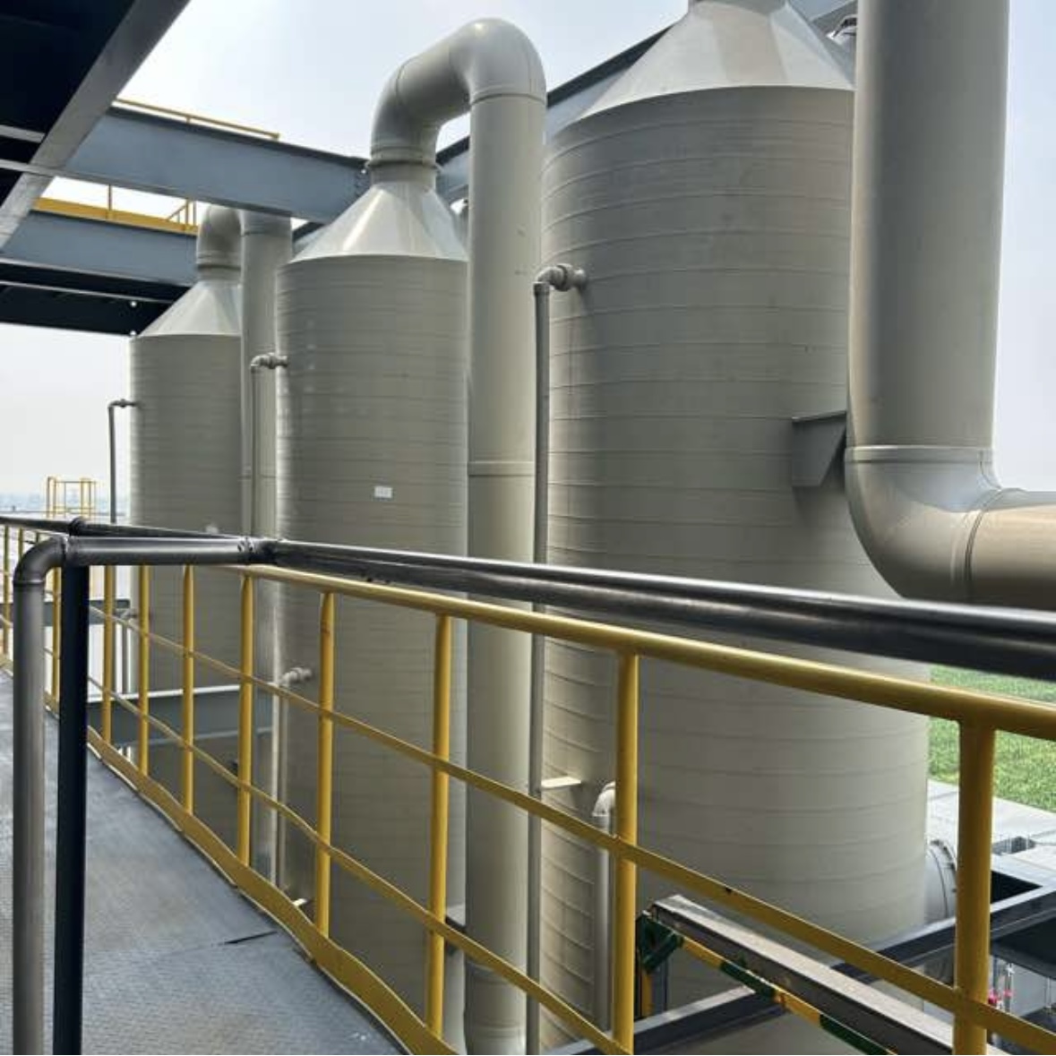
We have established a comprehensive product portfolio, featuring core offerings such as spray towers, activated carbon adsorption units, biological deodorization equipment, absorption towers, distillation columns, resin adsorption tanks, finned-tube heat exchangers, bag/cartridge dust collectors, and industrial fire-fighting water tanks. We provide solutions tailored to client requirements, ranging from individual units and modular systems to complete, turnkey engineering solutions.
In which industry sectors does the company have a deep focus, and what key environmental challenges can it help address?
With many years of deep engagement in the field of industrial environmental protection, we provide services across a wide range of sectors, including chemicals, pharmaceuticals, new energy, advanced materials, electronics manufacturing, mechanical processing, surface treatment, and food processing. We specialize in addressing complex challenges such as the treatment of VOC emissions, acid/alkali exhaust, corrosive chlorine-containing gases, particulate matter, and industrial odors (e.g., foul smells from wastewater basins), as well as providing solutions for industrial separation, purification, and waste heat recovery.
What core service capabilities does the company’s professional team possess?
The company boasts a professional team comprising environmental engineers, mechanical design engineers, process technicians, project managers, and international trade consultants. We possess the capability to provide end-to-end services—ranging from conceptual design, equipment selection, and system integration to project implementation—and are able to deliver customized technical solutions and on-site support tailored to specific operating conditions and environmental standards.
What are the corporate positioning and core business of Shijiazhuang Benchun Trading Co., Ltd.?
Located in Shijiazhuang, Hebei Province, China, the company is a comprehensive enterprise specializing in the export of industrial environmental protection equipment and engineering solutions. Integrating R&D and design, equipment manufacturing, international trade, engineering services, and technical support, the company is dedicated to providing global industrial clients with one-stop solutions—ranging from individual units to complete environmental protection systems.
Is the equipment prone to scaling or clogging?
Featuring a smooth stainless steel tower body and high-voidage structured packing, combined with an upstream filtration system, the unit effectively prevents clogging from impurities and is easy to clean and maintain.
Is it capable of handling various mixed organic solvent waste liquids?
Multi-stage distillation processes can be customized based on the boiling point differences of components in a mixed solvent, making them suitable for the purification of various organic waste liquid mixtures, including esters, alcohols, ketones, and hydrocarbons.
Is the equipment's energy consumption high, and what are the operating costs like?
Features intelligent, precise temperature control and thermal energy recycling; offers low energy consumption and automated, unattended operation—delivering long-term returns that far exceed maintenance and operating costs.
What level of purity can the solvent recovered from a distillation column reach?
Depending on the solvent composition, a purification level of 95%–99% can be achieved—fully meeting the standards for reuse within the production line and significantly reducing raw material procurement costs.
Does the intelligent system support remote monitoring?
Optional remote IoT monitoring functionality is available, enabling real-time viewing of water levels, water pressure, and equipment operating status, as well as remote early warning and remote control.
Is it suitable for outdoor, open-air installation?
The enclosure is UV-resistant, anti-aging, and weatherproof (windproof and rainproof); it features a specialized anti-corrosion design for outdoor use, allowing for long-term installation and operation in open-air environments.
What is the service life of the water tank, and is it prone to leaking?
Constructed from 304 stainless steel, the system offers a service life of over 15 years under normal use; its modular, precision-engineered assembly combined with a dual-layer sealing process completely eliminates any risk of water leakage or seepage.
Does the water tank comply with overseas industrial fire protection standards?
Our products are manufactured in strict accordance with international industrial fire safety standards. They meet all requirements regarding materials, water storage capacity, and pressure stabilization performance. We provide a complete set of qualification documentation to ensure a smooth inspection and acceptance process for our clients.
Can the equipment's dimensions and specifications be customized?
Full-specification customization is supported; designs and production can be tailored to individual client requirements regarding airflow, temperature, site conditions, and recovery needs.
How is the heat exchange efficiency, and are the energy-saving benefits significant?
Featuring a customized, high-efficiency heat exchange structure, the system achieves a heat exchange efficiency of over 95%. This significantly reduces wear and tear on downstream equipment, while the recovery and reuse of waste heat can lower production energy consumption by more than 30%.
Is it suitable for high-temperature, highly corrosive exhaust gases?
Available in 316L or 2205 stainless steel, these units are suitable for handling highly acidic, highly alkaline, or high-temperature corrosive exhaust gases; their fully anti-corrosive construction ensures a long service life.
Are finned heat exchangers prone to dust accumulation and clogging?
Featuring a design with widely spaced corrugated fins and smooth tube walls that resist fouling, the unit incorporates a detachable, easy-to-clean structure; this allows for the rapid removal of impurities and ensures consistent heat-transfer efficiency over long-term use.
Is the equipment noisy, and does it affect the factory environment?
Equipped with quiet, corrosion-resistant fans and an integrated noise-reduction design, the unit operates at low noise levels, making it perfectly suited for both production and office environments within a factory complex.
Will rainy weather or high temperatures affect the deodorizing performance?
The entire system is designed to withstand outdoor temperature extremes as well as rain and snow; its sealed configuration remains unaffected by weather conditions, ensuring stable performance of the microbial population and consistently meeting deodorization standards.
Does biological deodorization require frequent replacement of microbial strains?
The specialized deodorizing microbial consortia are self-replicating; under normal operating conditions, they require only periodic, small-scale replenishment rather than frequent replacement, resulting in extremely low operation and maintenance costs.
Is there a risk of water accumulation or damage to the sealed cover plate?
The cover plate features an arched design with an integrated drainage slope to prevent water accumulation. Made from FRP or PP, it offers excellent impact and aging resistance; it is durable, resistant to breakage or deformation, and comes with a warranty of over 10 years for outdoor use.
How safe is the vacuum desorption process?
Low-temperature vacuum desorption eliminates the risks associated with high temperatures and high pressures. Equipped with explosion-proof, pressure-relief, and alarm systems, the process ensures safe and stable operation in compliance with international industrial safety standards.
Can the equipment handle high-concentration chlorine-containing waste gas?
Multi-stage adsorption and multi-stage scrubbing processes can be customized based on exhaust gas concentration; these systems are suitable for handling chlorine-containing waste gas across a wide range of concentrations, consistently achieving treatment efficiencies of over 98%.
Do resin adsorption materials need to be replaced frequently?
The resin can be repeatedly regenerated via vacuum desorption; under normal operating conditions, it has a service life of 3–5 years, eliminating the need for frequent replacement and resulting in very low operation and maintenance costs.
Will chlorine-containing waste gas corrode the entire set of equipment?
The entire system features a fully anti-corrosive configuration, with tower bodies, adsorption tanks, fans, and ductwork constructed from 316 or 2205-grade stainless steel. Specifically designed to withstand chloride-ion-induced corrosion, the equipment offers a service life of 8–10 years under normal operating conditions.
What is the purity of the solvent recovered via distillation, and can it be reused directly?
Through multi-stage fractional distillation, the recovered solvent can reach a purity of over 95% and be fed directly back into the production line for reuse, effectively reducing the enterprise's raw material procurement costs.
Does the equipment have a large footprint, and is it suitable for a small factory?
The equipment features a modular, customizable design and supports compact layouts; specifications can be adjusted based on the dimensions of the client’s facility, making it suitable for production workshops of all sizes—large, medium, and small.
Does frequent desorption of activated carbon affect its service life?
Steam desorption temperatures are controllable, ensuring thorough desorption; under normal operating conditions, the system can be used repeatedly for 1–5 years, significantly reducing the costs associated with replacing consumables.
Can the treated mixed exhaust gas meet European and American environmental emission standards?
The comprehensive treatment process employs multi-stage purification and advanced treatment techniques, ensuring that concentrations of VOCs, acidic/alkaline substances, and particulate matter in the exhaust gas are consistently maintained within international emission standards. This solution complies with the environmental regulations of various regions—including the European Union, Southeast Asia, and the Middle East—and testing reports can be provided.
How can one prevent filter bags from being scratched or worn by the cage?
It should be verified that the longitudinal bars and circumferential rings are securely welded, with weld points and surfaces finished to be smooth. Additionally, ensure that the diameter and length of the filter cage are compatible with the filter bag. The presence of burrs, deformation, or rust on the surface of the filter cage may increase the risk of wear on the filter bag during both installation and operation.
How should one choose between a single-section filter cage and a multi-section plug-in (modular) filter cage?
A single-piece structure is suitable for equipment where length and transport conditions permit; a multi-section, plug-in (interlocking) design facilitates segmented transport and on-site assembly, making it appropriate for applications such as those involving longer filter bags. When making a selection, it is also necessary to ensure compatibility regarding the cage connection method, available installation space, and the structure of the filter bags.
What dimensions and structural configurations can be customized for filter cages?
The diameter ranges from φ100 to φ200 mm, with customizable lengths between 500 and 8000 mm. Specifications such as the number of longitudinal wires, wire diameter, spacing of transverse rings, top design, and connection method can also be selected according to requirements. When customizing, please verify the dimensions of the filter bags, the aperture size of the dust collector’s tube sheet, and the installation structure.
What is the difference between cold-galvanized and hot-galvanized filter cages?
Cold galvanizing produces a thinner zinc coating at a lower cost and is suitable for general operating conditions, such as dry environments at ambient temperatures. Hot-dip galvanizing, by contrast, provides a thicker zinc coating with superior moisture resistance, making it appropriate for applications involving standard boilers, cement production, metallurgy, and outdoor equipment. Neither method is suitable for environments exposed to strong acids, strong alkalis, or highly corrosive flue gases.
What are the common anti-corrosion treatments for filter cages?
Common types include cold galvanizing, hot-dip galvanizing, epoxy coating, silicone coating, and 304 stainless steel. Since each treatment method is suited to different temperature, humidity, and corrosive conditions, the choice should be based on the actual flue gas operating conditions.
What is the function of a filter cage in a fabric dust collector?
A filter cage—also known as a dust collector cage—consists of welded longitudinal wires and circumferential rings. It serves to support the filter bag, maintain its shape, and facilitate dust removal via pulse-jet cleaning. The quality of the welds and the surface treatment can also affect the installation of the filter bag and the risk of wear during operation.
What are the air handling capacities and models available for the absorption tower?
The provided data indicates an operating airflow range of 500–30,000 m³/h. Available models include the ABT-3000, ABT-8000, and ABT-15000, with corresponding airflow capacities of 3,000, 8,000, and 15,000 m³/h, respectively. Tower diameter, height, and material of construction can be customized based on specific operating conditions; final model selection should also take into account factors such as pollutant concentration, superficial gas velocity, and the absorption medium.
What materials are available for absorption towers, and what are their temperature ranges?
Materials such as rubber-lined carbon steel, PP, FRP (fiber-reinforced plastic), and 304/316L stainless steel can be evaluated based on specific operating conditions. Reference temperature ranges are as follows: PP ≤ 80°C, FRP ≤ 120°C, and stainless steel up to 300°C. The actual applicable temperature and corrosion resistance must be determined by considering the specific process medium, material specifications, and equipment design.
What are the structural configurations of absorption towers, and how should one be selected?
Common structural configurations include packed towers and tray towers. The selection process should take into account factors such as the exhaust gas flow rate, pollutant concentration, properties of the absorbent, target treatment requirements, and operating conditions; the gas-to-liquid ratio should also be determined based on the absorption medium and the specific project conditions.
What is the difference between an absorption tower and a spray tower?
Both methods utilize gas-liquid contact to treat waste gas. According to the provided information, the absorption tower can be either a packed tower or a tray tower, both of which are suitable for high-concentration waste gas and absorption processes in the fine chemical industry. The specific configuration and process design should be determined based on the composition of the waste gas, the treatment load, and the required absorption specifications.
How do absorption towers purify waste gas?
Exhaust gas enters the lower part of the tower and flows upward, while the absorbent is sprayed downward from the top, creating a countercurrent contact between the gas and liquid phases. Pollutants are transferred into the liquid phase and removed through dissolution or chemical reaction. The purified gas passes through a demister at the top of the tower before being discharged, while the absorbent liquid is either recirculated—with fresh reagents added as needed—or drained, depending on operational requirements.
What types of waste gases are absorption towers primarily used to treat?
Absorption towers can be used to treat acidic, alkaline, and other gaseous pollutants that are absorbable by liquids; examples include HCl, HF, NH₃, NOx, and certain soluble VOCs. Their actual applicability depends on the dissolution or reaction characteristics of the pollutants, as well as the choice of absorbent and the specific process conditions.
How should the material for a resin tank be selected?
The selection of materials must take into account the presence of acidic, alkaline, or corrosive components in the exhaust gas, as well as factors such as temperature, pressure, and chloride ion concentration. Carbon steel is a cost-effective option suitable for standard operating conditions. Whether stainless steel or 2205 duplex stainless steel is appropriate depends on the specific medium and corrosive environment; a general label of "corrosion-resistant" is insufficient for making a final selection.
What are the materials and specifications for resin tanks?
The vessel can be constructed from carbon steel, 304 or 316L stainless steel, or 2205 duplex stainless steel; the internal screen assembly and vessel dimensions can be customized according to project requirements. The RG-500, RG-1000, and RG-1500 models listed have air handling capacities of 1,000, 3,000, and 5,000 m³/h, respectively. Operating pressures and material specifications vary by model; please refer to the finalized technical proposal for specific details.
Can the resin tank operate continuously?
Multiple vessels can be operated in an alternating sequence—integrating adsorption, desorption, and cooling stages—to meet the requirements for continuous operation. The number of vessels required and the switching cycle are determined based on the exhaust gas flow rate, the adsorption capacity of the resin, and the regeneration process.
How do resin tanks adsorb and recover organic solvents?
Organic waste gas enters the vessel and passes through a resin bed, where organic components are adsorbed by the macroporous resin, and the treated gas is then discharged. Once the resin becomes saturated, it can be regenerated (desorbed) by introducing steam or hot nitrogen; the desorbed solvents are subsequently recovered via condensation. Following desorption, the resin bed is cooled with water, and the vessel returns to the adsorption operating mode.
What are resin tanks primarily used for?
The resin vessel is packed with macroporous resin, designed for the adsorption of gaseous media. In exhaust gas treatment, it can be used for the adsorption and enrichment of organic waste gases, as well as for the recovery of organic solvents. Its specific applicability depends on the composition of the waste gas and the type of resin used.
Which parameters can be customized for screen pipes?
Specifications may encompass outer diameter, length, slot size, open area ratio, number of support ribs, and material. Standard outer diameters typically range from 100 to 1500 mm, with lengths between 1000 and 6000 mm. For custom orders, it is recommended to provide equipment connection dimensions, filtration objectives, media conditions, and installation drawings.
What are the product forms of wedge-wire screen tubes?
The types listed include standard screen pipes, bridge-slotted screen pipes, pre-packed screen pipes, and multi-layer screen pipes. Each type features a different structure and is suited to different applications; determining whether a specific type is appropriate for a given filtration task requires considering both particle control requirements and the intended installation method.
What materials are available for screen pipes?
Common materials include 304, 304L, 316, and 316L stainless steel; depending on operating conditions, options such as duplex stainless steel, special alloys, or carbon steel with anti-corrosion treatments may also be evaluated. When selecting materials, it is essential to define the composition of the medium, temperature, corrosivity, and wear conditions, and to verify the suitability of the chosen material for the specific operating environment.
How should the slot width for a screen pipe be selected?
The slot size should be determined based on the dimensions of the particles to be retained, the medium being processed, and the specific filtration requirements. Typical slot sizes range from 0.1 to 15 mm, with the applicable range varying according to the outer diameter of the component. Final selection should also take into account the open area ratio, flow rate, and the structural design of the screen pipe.
In what types of equipment and industries are wedge-wire screen tubes primarily used?
It can be used in conjunction with resin tanks, adsorption towers, water treatment filters, and various tower internals. It is also suitable for applications in water treatment, the chemical industry, mining and metallurgy, oil and gas, and agricultural irrigation. Specific suitability should be determined based on the medium, particle characteristics, and equipment design.
What is a wedge-wire screen?
Wedge-wire screen tubes are cylindrical filtering elements constructed by continuously winding a V-shaped profile wire around axial support rods and welding it in place, creating a continuous slot that is wider on the outside and narrower on the inside. These screens can be installed within tanks, filters, or towers for applications such as filtration, water collection and distribution, resin retention, and solid-liquid separation.
What structural configurations and dimensions can be customized for wedge-wire screen panels?
Screen plates can be customized to meet specific equipment requirements—whether flat, curved, bent, or in a composite configuration—with tailored dimensions, gap sizes, aperture ratios, thicknesses, and materials. Providing equipment drawings, installation space details, the medium being processed, and specific screening requirements will help determine the precise specifications for the screen plates.
What materials are available for wedge-wire screen panels?
Common materials include 304, 304L, 316, and 316L stainless steel. Depending on operating conditions, options may also include duplex stainless steel, special alloys, or carbon steel with anti-corrosion surface treatment. When selecting materials, it is essential to verify the composition of the medium, its corrosivity, temperature, and wear conditions; material selection should not be based solely on industry-standard designations.
How should the slot width, open area ratio, and plate thickness for a screen plate be selected?
The slot width should be determined based on the target particle size for screening and the characteristics of the material. Factors such as the open area ratio, plate thickness, and support structure must also be considered in conjunction with the processing capacity, installation method, and loading conditions. The typical slot range provided in the documentation is 0.05–10 mm; however, actual specifications can be customized to meet specific requirements.
In which industries and processes can wedge-wire screen panels be used?
Suitable for dewatering and classification of minerals, coal, and aggregates; for use as curved screens or static screens in wastewater treatment; and for solid-liquid separation or filtration in industries such as chemicals, food processing, and pharmaceuticals. Specific suitability should be determined based on material properties, throughput, and process conditions.
What is the difference between wedge wire screen plates and wedge wire screen tubes?
Screen plates are flat or curved components suitable for planar screening applications that require a large filtration area, as well as for use as equipment linings. Screen tubes, by contrast, feature a cylindrical structure and differ in both their form and installation method. The specific choice depends on factors such as available equipment space, the direction of filtration, and the processing requirements.
What is a wedge-wire screen plate?
Wedge-wire screen panels are constructed by welding V-shaped profile wires onto support rods and can be fabricated into flat, curved, or bent configurations. The gaps on the screen surface are designed for screening, filtration, or the distribution of water or gas; these panels can be installed within tanks, vessels, or other types of equipment.
What information is required for the customization of a distillation column?
It is recommended to provide information such as feed composition and flow rate, target products and their purity requirements, operating pressure and temperature, material corrosivity, and available on-site space. Parameters including column diameter and height, the type of trays or packing, materials of construction, and auxiliary equipment—such as reboilers, condensers, and reflux drums—must be determined based on the specific material system and throughput.
What materials are available for distillation columns?
Materials include carbon steel, 304 and 316L stainless steel, titanium, and PTFE-lined components. Material selection should be based on the composition, corrosivity, temperature, and pressure of the process media. It is not advisable to determine suitability based solely on broad categories such as "strong acid" or "contains chlorides"; rather, corrosion resistance must be verified specifically for the actual medium in question.
Can a distillation column operate at atmospheric pressure, under vacuum, or under pressure?
Depending on the properties of the materials and the requirements of the process, the system can be designed for operation at atmospheric, reduced, or elevated pressure. Since operating pressure influences the boiling point of the materials, equipment construction, and auxiliary systems, it must be clearly defined during the selection phase and verified through process design calculations.
What are the structural configurations of a distillation column?
Either tray columns or packed columns may be selected. Tray columns include types such as sieve-tray, valve-tray, and bubble-cap columns, while packed columns can utilize either structured or random packing. The choice of column type should be determined based on the material system, throughput, separation requirements, and operating conditions.
What types of materials can a distillation column process?
This can be used for the separation of liquid mixtures in industries such as organic solvent recovery, fine chemicals, petrochemicals, pharmaceuticals, and food processing. Materials listed include methanol, ethanol, acetone, toluene, and ethyl acetate; however, the feasibility of effective separation must be evaluated based on the specific composition of the mixture, boiling points, and phase equilibrium data.
What is the separation principle of a distillation column?
A distillation column exploits the differences in volatility among the components of a mixture. Through heating and vaporization at the bottom, condensation at the top, and the reflux of a portion of the liquid, the rising vapor and descending liquid are brought into repeated contact on trays or packing, facilitating mass transfer. More volatile components tend to enter the vapor phase, while less volatile components tend to remain in the liquid phase; ultimately, these components are recovered separately from the top and bottom of the column.
What inspections and maintenance checks are required for fire-fighting water tanks?
The water-holding test shall last for 2–3 hours, with the absence of any leakage serving as the criterion for acceptance. Specific requirements for final acceptance, cleaning, and maintenance shall be determined based on the project design, applicable standards, and the material of the water tank. Additionally, the configuration of components—such as the liquid level control system, inlet and outlet pipes, overflow pipe, drain pipe, and maintenance access facilities—should also be inspected.
Can fire water tanks be installed on the roof, on the ground, or underground?
The installation location depends on the type of water tank, the building structure, and the fire protection system design. Options include elevated installation, ground-level placement, or—in the case of certain BDF (bolted-panel) water tanks—underground installation. Prior to actual installation, it is essential to verify the load-bearing capacity of the foundation, waterproofing measures, space for maintenance access, piping connections, and environmental conditions.
How do fire water tanks replenish their water supply and provide water to the fire protection system?
The water tank can be replenished via an inlet pipe, with the water level maintained at a set point by a float valve or a liquid-level control device. The outlet pipe is connected to fire pumps or the relevant piping network in accordance with the design. Provisions for overflow, drainage, ventilation, access manholes, ladders, and liquid-level monitoring shall be determined based on the tank structure and project design specifications.
How are the capacity and dimensions of a fire water tank determined?
The capacity and dimensions of a water tank must be determined based on the fire protection system design, the intended use of the building, available installation space, and relevant regulatory requirements. For the ZYB series of stainless steel tanks, the available specifications range from 1 m³ to 504 m³; other product types may have different ranges. The final capacity, dimensions (length, width, and height), and plate thickness shall be in accordance with the project design and the confirmed technical documentation.
What are the types and materials of fire-fighting water tanks?
Available options include stainless steel prefabricated welded water tanks, SMC (fiberglass-reinforced plastic) modular water tanks, porcelain-enameled steel water tanks, powder-coated steel water tanks, hot-dip galvanized steel water tanks, and BDF stainless steel composite panel water tanks. These types differ in terms of structure, installation method, corrosion resistance, and suitable applications; the selection should be based on specific project requirements.
What is the primary function of a fire water tank?
A fire water tank is used to store water for firefighting purposes and, in accordance with the design of the fire water supply system, delivers water to the relevant piping network or fire pumps. It serves to provide a water supply during the initial stages of a fire; the specific supply method and storage capacity must be determined based on the fire protection design for the building.
What are the temperature and pressure ranges for finned-tube heat exchangers?
The operating temperature range is -20°C to 400°C, with a tube-side pressure of ≤1.6 MPa; high-pressure versions can also be customized. The specific scope of application depends on the materials, construction, and design conditions; the final parameters shall be as specified in the project design documentation.
What materials can be chosen for heat exchanger tubes and fins?
Heat exchanger tubes can be made of 304 or 316L stainless steel, or carbon steel; fins can be made of aluminum, stainless steel, or copper. Since different materials vary in terms of temperature suitability, corrosion resistance, and cost, the choice should be determined based on the media inside and outside the tubes, operating temperatures, and specific project requirements.
What parameters need to be provided for model selection?
It is recommended to provide the following information: airflow rate or required heat transfer capacity, air inlet and outlet temperatures, the medium inside the tubes along with its inlet and outlet temperatures, operating pressure, medium composition, allowable pressure drop, available installation space, and site environmental conditions. These parameters influence the heat transfer area, fin spacing, number of tube rows, number of tube passes, and material specifications.
Can finned heat exchangers heat and cool air?
Yes. For heating, the system can be designed to use heat transfer media such as steam, hot water, or thermal oil; for cooling, cold water or a refrigerant can be used. The specific medium, inlet and outlet temperatures, and required heat transfer capacity should be clearly defined during the equipment selection process.
How does a finned heat exchanger work?
A heating medium—such as hot water, steam, or thermal oil—flows through heat-exchange tubes, transferring heat to the surrounding air via the tube walls and fins. Driven by a fan, the air passes over the finned tube bundle and increases in temperature. Conversely, if cold water or a refrigerant is circulated through the tubes, the system can be used to cool the air or other process media.
What are finned heat exchangers primarily used for?
Finned-tube heat exchangers facilitate heat transfer between a fluid medium inside the tubes and the air outside, and can be used for air heating, air cooling, and the recovery of waste heat from flue gases. Common applications include industrial drying, HVAC heating, process air treatment, and the utilization of waste heat from boilers or kilns.
Can anti-static or flame-retardant filter cartridges, on their own, ensure safety regarding dust?
No. While anti-static filter cartridges can reduce the risk of static electricity accumulation and flame-retardant cartridges can delay combustion, this does not mean the entire system is explosion-proof or fully fireproof. When handling flammable or explosive dust, or in operating environments where sparks may be present, the filter cartridges, dust collection equipment, and associated safety configurations must be evaluated by the project designers.
How can I determine the dimensions of a filter cartridge and whether it is compatible with my existing equipment?
It is necessary to verify the filter cartridge’s outer diameter, inner diameter, height, end cap configuration, sealing method, and mounting structure, while also confirming the dimensions of the equipment’s tube sheet and available space. While a range of standard specifications is listed, customization based on equipment model, samples of existing filter cartridges, or technical drawings is also available. Please note that similar dimensions alone do not guarantee compatibility for installation.
What is the difference between standard polyester filter cartridges and membrane-coated filter cartridges?
Standard polyester filter cartridges are suitable for a wide range of typical industrial dusts. Membrane-coated polyester filter cartridges feature a microporous PTFE membrane bonded to the substrate surface; these are reportedly better suited for fine dust and applications with stricter emission requirements. The actual filtration performance, however, also depends on the specific characteristics of the dust, the equipment design, and operational parameters.
What are the common materials and types of filter cartridges?
Common types include wood pulp fiber, polyester fiber, membrane-coated polyester, anti-static, flame-retardant, and PTFE filter cartridges. Each filter medium offers specific advantages regarding moisture resistance, temperature tolerance, dust-cleaning performance, and anti-static properties; the choice should be based on the characteristics of the dust and the operating conditions of the equipment.
What role do dust filter cartridges play in the equipment?
Filter cartridges serve as the core filtration components in pulse-jet cartridge dust collectors, grinding dust extraction workstations, and welding fume purification equipment. Their pleated filter media create a folded structure that increases the filtration surface area within a confined space, enabling the capture of particulate matter from dust-laden air streams.
What are the dust removal efficiency and filtration method of the equipment?
The filtration efficiency is ≥99.5%, with an outlet concentration of ≤10 mg/m³. Filter cartridge options include polyester media, PTFE-membrane-coated media, or anti-static media. Actual performance may vary based on factors such as dust characteristics, filter media configuration, operating airflow, and equipment sealing; specific performance metrics shall be determined by the project design and test results.
For what types of dust and operating conditions are grinding and dust-extraction workstations suitable?
Suitable for dry operating conditions at ambient temperature; the specified parameters are a temperature of ≤60°C and a system negative pressure of ≤3000 Pa. It is not suitable for applications involving high temperatures, high humidity, high moisture or oil content, or dust that is highly adhesive and prone to clogging the filter media.
What are the available dimensions and workstation configurations for the workbenches?
There are two common configurations: single-station and dual-station. The single-station unit measures 2400 × 1600 × 2400 mm, while the dual-station unit measures 2400 × 3200 × 2400 mm. Workbench dimensions, height, and enclosure configuration can be customized based on the specific site layout and operational requirements.
How do sanding and dust-removal workstations collect and purify dust?
When a workpiece is being processed on the work surface, dust is drawn into the unit through the intake vents by means of negative pressure. Larger particles settle into the dust collection drawer at the bottom, while finer particles are captured by the filter cartridges. As dust accumulates on the cartridges, a pulse-jet cleaning system clears the filter media surface, causing the dislodged dust to fall into the drawer for convenient periodic removal.
For which processes are grinding and dust-extraction workstations suitable?
Suitable for dry, dust-generating workstations—such as those involving metal grinding, casting polishing, weld seam grinding, deburring, and small-scale cutting—this equipment can be used for the on-site collection of dust, including iron filings, aluminum shavings, plastics, and composite material particles. Specific suitability should be determined based on the characteristics of the dust and on-site safety requirements.
What models of cartridge dust collectors are available, and which parameters should be considered when selecting one?
Typical operating air volumes range from 3,000 to 15,000 m³/h, with filtration areas between 50 and 270 m² and 6 to 32 filter cartridges. Equipment selection should also account for factors such as dust type, air volume, filtration velocity, available installation space, the dust-cleaning mechanism, and compressed air specifications; the final equipment configuration must be calculated based on the specific operating conditions of the project.
For what temperature and humidity conditions are cartridge dust collectors suitable?
Primarily intended for applications involving dust under ambient temperature, dry, and low-humidity conditions. If the dust is at a high temperature, has high humidity, or is corrosive, it is necessary to evaluate the suitability of the filter media and equipment materials; the specific temperature range should be determined based on the filter media and the operating conditions.
How fine a dust particle can a cartridge dust collector filter out? What is its dust removal efficiency?
The equipment is capable of capturing particles 0.3 μm and larger, with a design performance of ≥99.9% dust removal efficiency and an outlet concentration of ≤10 mg/m³. Actual performance may be influenced by factors such as the nature of the dust, the filter media used, the filtration velocity, equipment sealing, and operating conditions; specific performance metrics should be determined based on project design specifications and test results.
How do pulse-jet cartridge dust collectors perform filtration and dust cleaning?
Once the dust-laden gas enters the equipment, large dust particles settle into the hopper, while finer dust is captured by the filter media of the filter cartridges. As dust accumulates on the cartridges, a pulse system—triggered either at set intervals or based on resistance thresholds—discharges compressed air, dislodging the collected dust so that it falls into the hopper.
What types of dust are primarily handled by pulse-jet cartridge dust collectors?
Suitable for applications involving dry, fine dust, welding fumes, grinding dust, laser-cutting dust, plastic dust, and airborne particles generated during the feeding of powdered materials. Actual suitability should be determined based on specific dust characteristics, temperature, humidity, and the production process.
How should one select a model for a bag filter?
When selecting equipment, it is necessary to first determine the air volume to be handled, the characteristics of the dust, the flue gas temperature, and the target emission requirements. Subsequently, verify the filtration area, filtration velocity, specifications and quantity of filter bags, the dust-cleaning configuration, and the equipment's pressure drop. Other dimensions, materials, and accessories can be customized according to specific operating conditions.
What are the dust removal efficiency and outlet concentration of a bag filter?
The dust removal efficiency is ≥99.5%, and the outlet concentration is ≤10 mg/m³. Actual results may be influenced by factors such as the properties of the dust, the material of the filter bags, the filtration velocity, the sealing of the equipment, and the operating conditions; specific performance metrics should be determined based on project design specifications and test results.
What is the maximum flue gas temperature that a fabric filter (baghouse) can handle?
The applicable temperature range depends on the material of the filter bag. Standard-temperature filter bags are generally rated for temperatures up to 120°C, while high-temperature versions can withstand up to 260°C. The specific filter medium and its upper temperature limit should be determined by considering the flue gas temperature, humidity, and the characteristics of the dust.
How does a pulse-jet bag filter work?
As dust-laden gas enters the middle chamber, dust particles are trapped on the outer surfaces of the filter bags. The cleaned gas passes through the filter bags into the clean-air chamber and is then discharged. As dust accumulates on the filter bags and the equipment's resistance increases, the pulse control system triggers the solenoid pulse valves; compressed air is then injected into the filter bags, dislodging the accumulated dust, which falls into the hopper and is subsequently removed by the dust discharge mechanism.
What are baghouse dust collectors primarily used for?
Baghouse dust collectors capture solid particles from dust-laden gas streams using filter bags; they are suitable for industrial dust control and the recovery of powdered materials. Common applications include woodworking, construction materials, metallurgy, mining, grain processing, boiler flue gas treatment, as well as processes such as material conveying, packaging, screening, and feeding.
What are the collection efficiency and applicable temperature range for the gas-collection cover plate?
Product documentation specifies a containment/collection efficiency of ≥98% and an applicable temperature range of -20°C to 180°C; the exact range depends on the specific material and operating conditions. Actual collection efficiency may be influenced by factors such as on-site sealing, negative-pressure system performance, the presence of openings, and installation quality. It is recommended to rely on project-specific design specifications and test results.
How should the material for a resin tank be selected?
Material selection must take into account the presence of acidic, alkaline, or corrosive components in the exhaust gas, as well as factors such as temperature, pressure, and chloride ion concentration. Carbon steel is a cost-effective option suitable for standard operating conditions. Whether stainless steel or 2205 duplex stainless steel is appropriate depends on the specific medium and corrosive environment; the general term "corrosion-resistant" is insufficient for making a final selection.
What are the materials and specifications for resin tanks?
The vessel can be constructed from carbon steel, 304 or 316L stainless steel, or 2205 duplex stainless steel; the internal screen assembly and vessel dimensions can be customized according to project requirements. The RG-500, RG-1000, and RG-1500 models listed have air handling capacities of 1,000, 3,000, and 5,000 m³/h, respectively. Operating pressures and material specifications vary by model; please refer to the finalized technical proposal for specific details.
Can the resin tank operate continuously?
Multiple vessels can be operated in an alternating sequence—integrating adsorption, desorption, and cooling stages—to meet the requirements for continuous operation. The number of vessels required and the switching cycle are determined based on the exhaust gas flow rate, the adsorption capacity of the resin, and the regeneration process.
How do resin tanks adsorb and recover organic solvents?
Organic waste gas enters the vessel and passes through a resin bed, where organic components are adsorbed by the macroporous resin, and the treated gas is then discharged. Once the resin becomes saturated, it can be regenerated by introducing steam or hot nitrogen; the desorbed solvents are subsequently recovered via condensation. Following desorption, the resin bed is cooled with water, and the vessel returns to the adsorption phase.
What are resin tanks primarily used for?
The resin vessel is packed with macroporous resin, designed for the adsorption of gaseous media. In exhaust gas treatment, it can be used for the adsorption and enrichment of organic waste gases, as well as for the recovery of organic solvents. Its specific applicability should be determined based on the composition of the waste gas and the type of resin used.
What is the deodorization efficiency of a biological deodorization unit, and what auxiliary systems are required?
The odor removal efficiency is ≥95%; the system is equipped with a circulating spray mechanism and liquid-level control. Actual performance may vary depending on the composition, concentration, and temperature of the exhaust gas, as well as specific operating conditions; these factors should be verified based on project-specific testing and applicable emission requirements.
What are the available models and packing heights for biological deodorization units?
The models listed include the BOT-5000, BOT-10000, and BOT-20000, with corresponding air volumes of 5,000, 10,000, and 20,000 m³/h, respectively. The packing heights are 1200 mm for the BOT-5000, and 1200–1500 mm for both the BOT-10000 and BOT-20000. The unit dimensions, materials, and packing configuration can be determined or customized based on specific project requirements and operating conditions.
What is the treatment air volume range for a biological deodorization unit?
The equipment’s air treatment capacity ranges from 500 to 100,000 m³/h; larger specifications can also be customized based on project requirements. The specific model should be determined by considering factors such as the exhaust gas flow rate, the nature of the pollutants, the required residence time, and on-site installation conditions.
For what temperature ranges and exhaust gas conditions are biological deodorization units suitable?
The provided data specifies an inlet air temperature range of 15–40°C. The waste gas must not contain highly bactericidal or toxic substances, as these could impair microbial activity. For actual projects, it is also necessary to verify the composition and concentration of the waste gas, as well as other operating conditions that might affect the biological treatment process.
How do biological deodorization units purify waste gas?
The malodorous waste gas first passes through a pre-scrubbing stage, where it is humidified and its temperature is adjusted, before entering a biological filter bed. Microorganisms on the surface of the packing material adsorb and decompose the odorous components in the waste gas, converting them into substances such as carbon dioxide, water, and inorganic salts. A spray system is used to maintain the moisture level of the packing material, providing a suitable environment for the microorganisms.
What types of malodorous gases are primarily treated by biological deodorization units?
It is primarily used for treating malodorous gases such as hydrogen sulfide, ammonia, and mercaptans; it can also be applied to low-concentration VOCs containing readily biodegradable components. Its specific suitability should be evaluated based on the composition, concentration, and biodegradability of the waste gas.
What is the difference between an activated carbon adsorption tank and an activated carbon adsorption box?
Adsorption tanks feature a vertical vessel design equipped with valves and piping, making them suitable for closed-loop processes, desorption/regeneration, and solvent recovery systems. Adsorption units, by contrast, utilize a modular, drawer-style configuration and are typically employed in purification processes that require periodic replacement of the activated carbon. The selection between these options should be based on an assessment of factors such as airflow volume, exhaust gas concentration, the need for solvent recovery, and the specific operational requirements.
What are the materials and specifications for activated carbon adsorption tanks?
Available material options include anti-corrosion treated carbon steel, 304 stainless steel, or 316L stainless steel. The VCA-G1000, VCA-G3000, and VCA-G5000 models listed have air treatment capacities of 1,000, 3,000, and 5,000 m³/h, respectively. Specific vessel dimensions, materials, and pressure parameters are determined based on the model and project requirements.
What is the applicable temperature range for an activated carbon adsorption tank?
The product specifications indicate an exhaust gas temperature of ≤80°C. Actual operating conditions must be determined by taking into account the composition of the exhaust gas, the characteristics of the activated carbon, and the specific adsorption and desorption processes.
Can an activated carbon adsorption tank operate continuously?
Continuous operation can be achieved by switching between multiple vessels, allowing for adsorption and desorption processes to take place across different units. Whether the system can meet a 24-hour operational requirement must be verified during the design phase, based on factors such as the exhaust gas flow rate, adsorption cycle duration, desorption and cooling times, and the specific configuration of the vessels.
How is solvent recovery achieved using an activated carbon adsorption tank?
As organic waste gas passes through a bed of granular activated carbon within a vessel, the organic components are adsorbed. Once the activated carbon becomes saturated, it can be regenerated by introducing steam or hot nitrogen; the desorbed solvents are then recovered using auxiliary equipment such as condensers. The specific regeneration method and recovery efficiency depend on the properties of the solvents and the design of the system.
What kind of waste gas are activated carbon adsorption tanks primarily used to treat?
Primarily used for the treatment of organic waste gas with low to medium flow rates; it is particularly well-suited for applications involving the recovery of organic solvents or processes where the adsorbent can be desorbed and regenerated. It is applicable for concentrations ranging from 200 to 20,000 mg/m³; however, its actual suitability should be determined based on the specific composition of the waste gas and the process conditions.
Can an activated carbon adsorption unit be used in combination with other exhaust gas treatment equipment?
It can be used independently or integrated in series with equipment such as a spray tower, UV system, or RTO, serving as a downstream advanced purification unit. The specific configuration sequence and treatment performance should be evaluated based on the composition and concentration of the waste gas, as well as the overall process requirements.
How should activated carbon be handled once it reaches saturation through adsorption?
Once the activated carbon reaches adsorption saturation, the filter cartridge can be removed and the activated carbon replaced to restore the equipment's treatment capacity. The replacement frequency depends on factors such as the composition and concentration of the waste gas, the airflow rate, and the duration of operation; it should be determined based on actual usage conditions.
What temperature and humidity conditions are suitable for activated carbon adsorption units?
The provided documentation specifies an exhaust gas temperature of ≤60°C; the equipment is not suitable for operating conditions characterized by high temperatures, high oil-mist concentrations, or high humidity. If the relative humidity exceeds 70%, a pre-dehumidification stage is required. Specific operational limits should be determined based on the actual exhaust gas conditions and the equipment design.
What forms of activated carbon are used in activated carbon adsorption units?
The unit can be loaded with either honeycomb activated carbon or granular/columnar activated carbon. It utilizes a drawer-style filter cartridge design, which facilitates easy installation, removal, and replacement. The specific type of activated carbon to be used should be determined based on factors such as the composition of the exhaust gas, the airflow volume, and the equipment configuration.
How does an activated carbon adsorption unit purify waste gas?
After entering the unit, the exhaust gas passes through a bed of activated carbon, where organic molecules and odorous substances are adsorbed and trapped within the micropores of the carbon. The treated gas is then discharged through the outlet. The movement of the gas is driven by the system's induced-draft fan.
What types of waste gas are primarily treated by activated carbon adsorption units?
Primarily used for the treatment of organic waste gases and odorous gases characterized by low concentrations and high flow rates; the applicable VOC concentration specified in the documentation is ≤800 mg/m³. Suitability should be further verified based on the specific composition of the waste gas, its concentration, and the operating conditions.
How should a spray tower be maintained?
Equipment maintenance involves the inspection and replacement of components such as access manholes, packing, and spray nozzles. The management of circulating fluid, chemical dosing, and cleaning intervals should be determined based on the specific exhaust gas conditions and the operational status of the equipment.
What is the purification efficiency of a spray tower?
The reference values provided in the product documentation indicate an efficiency of ≥95% for the purification of acidic/alkaline exhaust gases, and an efficiency of ≥99% for the removal of liquid droplets larger than 10 μm. Actual performance may vary depending on the specific pollutants, absorption liquid, operating parameters, and testing conditions; therefore, project-specific design specifications and test results should be taken as the definitive criteria.
What is the treatment air volume range for a spray tower?
The product documentation specifies an operating air volume range of 500–100,000 m³/h. The specific model should be selected based on the required air volume, the composition and temperature of the exhaust gas, and the specific treatment requirements.
What materials are available for spray towers, and what is their temperature range?
Available material options include PP, FRP (fiber-reinforced plastic), and 304/316L stainless steel. Reference temperature ranges are as follows: PP ≤ 80°C, FRP ≤ 120°C, and stainless steel ≤ 300°C. The actual upper operating limit must be determined based on the specific medium, its corrosivity, and the equipment design.
Can a spray tower handle VOCs?
Spray towers can be used for the pretreatment of certain water-soluble VOCs; however, this does not imply that they are capable of treating all types of VOCs on their own. The actual effectiveness must be evaluated based on the specific types and concentrations of the VOCs, as well as the subsequent treatment processes.
What types of acidic or alkaline gases can a spray tower handle?
The substances listed as applicable include HCl, HF, NH₃, H₂SO₄ acid mist, and NOx. As different gases require different absorption liquids and operating conditions, the design scheme should be determined based on the actual composition of the waste gas.
What is the working principle of a spray tower?
Exhaust gas enters the lower part of the tower and flows upward, while the absorbing liquid is sprayed from the top and flows downward. As the gas and liquid come into contact within the packed section, pollutants are captured by the absorbing liquid; the purified gas then passes through a mist eliminator to remove any entrained droplets.
What kind of waste gas are spray towers primarily used to treat?
Spray towers are primarily used for treating acidic or alkaline gases, water-soluble pollutants, and for the pre-treatment of certain dust-laden exhaust streams. Their suitability for specific pollutants must be determined by considering the composition and concentration of the exhaust gas, as well as the choice of absorption liquid.
No matching FAQs found.


Contact us
If you have questions or need help, contact our team for dedicated support.
We look forward to hearing from you
Submit
Online
Send email